0755-86344580
浪涌/脉冲保护对于所有电路设计都是必不可少的。SWR系列,尺寸从0402-2512,容差5%~10%,1ohm~20Mohm。更多的电路设计变得越来越重要。浪涌/脉冲保护对于所有电路设计都是必不可少的。Viking 的 SWR 系列,未修整的电阻层仍然是卓越的脉冲和 ESD 耐受电阻,适用于保护电子电路免受极端脉冲和浪涌的影响。在瞬间施加大电流或施加ESD的电路中,需要耐受脉冲或浪涌的电阻器。浪涌意味着过载,如 ESD 或持续时间较短的高压。防浪涌电阻器可以防止瞬间施加的大功率造成的损坏。
0402 / 0603 / 0805 / 1206 / 1210 / 2010 / 2512
耐浪涌贴片电阻器 - SWR 系列 文件下载
降额曲线
浪涌/脉冲保护对于所有电路设计都是必不可少的。SWR系列,尺寸从0402-2512,容差5%~10%,1ohm~20Mohm。更多的电路设计变得越来越重要。浪涌/脉冲保护对于所有电路设计都是必不可少的。Viking 的 SWR 系列,未修整的电阻层仍然是卓越的脉冲和 ESD 耐受电阻,适用于保护电子电路免受极端脉冲和浪涌的影响。在瞬间施加大电流或施加ESD的电路中,需要耐受脉冲或浪涌的电阻器。浪涌意味着过载,如 ESD 或持续时间较短的高压。防浪涌电阻器可以防止瞬间施加的大功率造成的损坏。
征
• 高额定功率。
• 优异的浪涌耐受和脉冲耐受性能。
• 提高工作电压额定值。
• 标准封装尺寸0402~2512。
• AEC-Q200 合规性。
应用
• 计量(测试/测量)
• 医疗设备
• 汽车
• 电源供应
• 充电器
• 逆变器
• 液晶视频监视器
建造
零件编号
标准电气规格
项目
类型
70°C 时的额定功率 工作温度
范围 限度。
工作电压 限度。
过载电压 阻力范围 TCR
(PPM/°100)
±5% ±10% ±20%
SWR02 (0402) 1/5W -55 ~ +155°C 50V 100V 1Ω -20Ω ±300
22Ω - 1MΩ ±100
SWR03 (0603) 1/8W -55 ~ +155°C 50V 100V 10Ω - 270Ω ±200
300Ω - 1MΩ ±100
SWR05 (0805) 1/4W -55 ~ +155°C 150V 300V 1Ω - 270Ω ±200
300Ω - 20MΩ ±100
SWR06 (1206) 1/3W -55 ~ +155°C 200V 400V 1Ω - 20Ω ±200
22Ω - 20MΩ ±100
SWR13 (1210) 1/2W -55 ~ +155°C 200V 400V 1Ω - 20Ω ±200
22Ω - 20MΩ ±100
SWR10 (2010) 3/4W -55 ~ +155°C 400V 800V 1Ω - 20Ω ±200
22Ω - 20MΩ ±100
SWR12 (2512) 1.5W -55 ~ +155°C 500V 1000V 1Ω - 20Ω ±200
22Ω - 20MΩ ±100
工作电压=√(P*R) 或。上面列出的工作电压,以较低者为准。
过载电压=2.5*√(P*R) 或 Max. 上面列出的过载电压,以较低者为准。
额定功率取决于电阻元件的温度。由于电阻器的功率耗散,电阻元件的温度会根据 PCB 的散热情况而升高。应用中的额定功率仅适用于电阻元件的温度不超过 155°C 的情况。
☑ Viking 能够根据客户的要求制造可选规格。
脉冲承受能力
单脉冲图是每隔一分钟施加 50 个矩形脉冲的结果。可接受的极限是电阻从初始值的偏移小于 1%。施加的功率受所示允许脉冲电压图的限制。
连续脉冲
连续负载图是通过应用重复的矩形脉冲获得的,其中脉冲周期经过调整,使得电阻器中耗散的平均功率等于其在 70°C 时的额定功率。再次接受的极限是电阻从初始值的变化小于 1%。
闪电浪涌
电阻器根据 IEC 60115-1 使用 1.2/50us 和 10/700 脉冲波形进行测试。可接受的极限是电阻从初始值的偏移小于 1%。
Surge Withstanding Chip Resistor - SWR Series Files Download
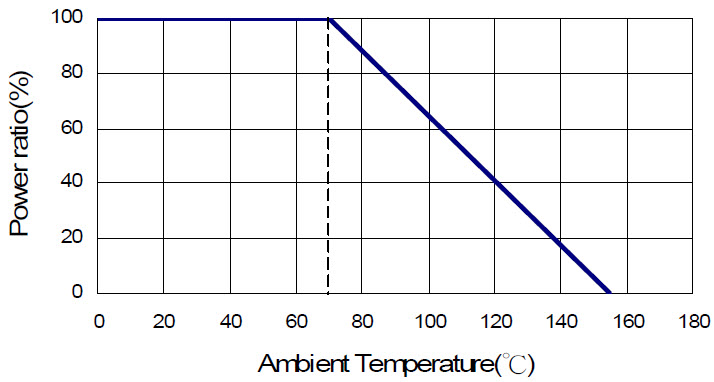
Derating Curve
Excellent Surge withstanding chip resistor , high power is available.
High power rating.
Excellent surge withstanding & pulse withstanding performance.
Improved working voltage ratings.
Standard package sizes of 0603~2512.
AEC-Q200 Compliance.
Metering (Testing/Measurement)
Medical Devices
Automotive
Power supply
Charger
Inverter
LCD Video Monitors


|
Item Type |
Power Rating at 70°C |
Operating Temp. Range |
Max. Operating Voltage |
Max. Overload Voltage | Resistance Range |
TCR (PPM/°C) | ||
|---|---|---|---|---|---|---|---|---|
| ±5% | ±10% | ±20% | ||||||
| SWR03 (0603) | 1/8W | -55 ~ +155°C | 50V | 100V | 10Ω - 270Ω | ±200 | ||
| 300Ω - 1MΩ | ±100 | |||||||
| SWR05 (0805) | 1/4W | -55 ~ +155°C | 150V | 300V | 1Ω - 270Ω | ±200 | ||
| 300Ω - 20MΩ | ±100 | |||||||
| SWR06 (1206) | 1/3W | -55 ~ +155°C | 200V | 400V | 1Ω - 20Ω | ±200 | ||
| 22Ω - 20MΩ | ±100 | |||||||
| SWR13 (1210) | 1/2W | -55 ~ +155°C | 200V | 400V | 1Ω - 20Ω | ±200 | ||
| 22Ω - 20MΩ | ±100 | |||||||
| SWR10 (2010) | 3/4W | -55 ~ +155°C | 400V | 800V | 1Ω - 20Ω | ±200 | ||
| 22Ω - 20MΩ | ±100 | |||||||
| SWR12 (2512) | 1.5W | -55 ~ +155°C | 500V | 1000V | 1Ω - 20Ω | ±200 | ||
| 22Ω - 20MΩ | ±100 | |||||||
Operating Voltage=√(P*R) or Max. Operating Voltage listed above, whichever is lower.
Overload Voltage=2.5*√(P*R) or Max. Overload Voltage listed above, whichever is lower.
☑ Viking is capable of manufacturing the optional spec based on customer's requirement.
The single impulse graph is the result of 50 impulses of rectangular shape applied at one-minute intervals. The limit of acceptance was a shift in resistance of less than 1% from the initial value. The power applied was subject to the restrictions of the maximum permissible impulse voltage graph shown.
The continuous load graph was obtained by applying repetitive rectangular pulses where the pulse period was adjusted so that the average power dissipated in the resistor was equal to its rated power at 70°C. Again the limit of acceptance was a shift in resistance of less than 1% from the initial value.
Resistors are tested in accordance with IEC 60115-1 using both 1.2/50us and 10/700 pulse shapes. The limit of acceptance is a shift in resistance of less than 1% from the initial value.
