0755-86344580
圆柱型电阻:高精度,低温漂(TCR)/低温度系数,阻值误差小,体积小,过电流能力强,阻值范围宽等特点 尺寸:0204,0207 阻值范围:0.1Ω~10MΩ 精度:0.1%,0.25%,0.5%,1%,5% 温度系数(TCR):10PPM/℃,15PPM/℃,25PPM/℃,50PPM/℃,100PPM/℃ 功率:1/4W,2/5W,1/2W,1W
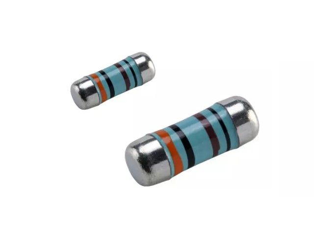
CSR 晶圆电阻(圆柱型金属膜电阻) 色环贴片电阻
CSRV 汽车级晶圆电阻(车规级金属膜电阻) 车规色环贴片电阻
CSRH 高压晶圆电阻(高电压色环电阻) 高压色环贴片电阻
CSRP 精密高压晶圆电阻(高电压晶圆电阻)
Metal Film Precision Resistor - CSR Series Files Download
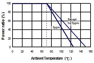
Derating Curve
Metal film precision MELF resistor. Thin film with excellent stabilit , Sn termination on Ni barrier, tight tolerance and low TCR , precision MELF resistor, SMD enabled structure.
Excellent overall stability.
Tight tolerance down to ±0.1%.
Extremely low TCR down to ±10 PPM/°C.
High power rating up to 1 Watts.
Telecommunication
Medical Equipment
Measurement/Testing Equipment
| Type | Power Rating at 70°C | Operating Temp. Range | Max. Operating Voltage | Max. Overload Voltage | Resistance Range | TCR (PPM/°C) | ||||
|---|---|---|---|---|---|---|---|---|---|---|
| ±0.1% | ±0.25% | ±0.5% | ±1% | ±5% | ||||||
| 0204 | 1/4W | -55 ~ +155°C | 200V | 400V | 10Ω-20KΩ | ±10 | ||||
| 10Ω-300KΩ | ±15 | |||||||||
| 10Ω-1MΩ | 4.02Ω-4.7MΩ | |||||||||
| 10Ω-1MΩ | 1Ω-1MΩ | |||||||||
| - | 0.1Ω-10MΩ | |||||||||
| Jumper:2A | 0Ω(<15mΩ) | - | ||||||||
| 0207 | 1/2W | -55 ~ +155°C | 300V | 600V | 10Ω-20KΩ | ±10 | ||||
| 10Ω-300KΩ | ±15 | |||||||||
| 10Ω-1MΩ | 4.02Ω-4.7MΩ | |||||||||
| 10Ω-1MΩ | 1Ω-1MΩ | |||||||||
| - | 0.1Ω-10MΩ | |||||||||
| Jumper:4A | 0Ω(<15mΩ) | - | ||||||||
The single impulse graph is the result of 50 impulses of rectangular shape applied at one-minute intervals. The limit of acceptance was a shift in resistance of less than 1% from the initial value. The power applied was subject to the restrictions of the maximum permissible impulse voltage graph shown.
The continuous load graph was obtained by applying repetitive rectangular pulses where the pulse period was adjusted so that the average power dissipated in the resistor was equal to its rated power at 70°C. Again the limit of acceptance was a shift in resistance of less than 1% from the initial value.
Resistors are designed to function according to ohmic laws. This is basically true of resistors for frequencies up to 100kHz. At higher frequencies, there is an additional contribution to the impedance by an ideal resistor switched in series with a coil and both switched parallel to a capacitor. The values of the capacitance and inductance are mainly determined by the dimensions of the terminations and the conductive path length.
The environment surrounding components has a large influence on the behavior of the component on the printed-circuit board.
Resistors are tested in accordance with IEC 60 115-1 using both 1.2/50us and 10/700us pulse shapes. The limit of acceptance is a shift in resistance of less than 0.5% from the initial value.
