0755-86344580
0102 / 0204 / 0207
汽车级金属膜精密MELF电阻器 - CSRA系列 文件下载
降额曲线
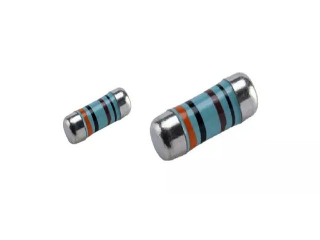
MELF 为圆柱形,带有金属电极无引线面电阻器。焊盘图案尺寸与 SMD 贴片电阻器相同。
它是通过在高级陶瓷体上沉积均匀的 NiCr 薄膜来制造的。高质量的 MELF 电阻器提供出色的电气和环境稳定性,在整个使用寿命、偏湿度和短时间过载测试中表现出卓越的稳定性。
交货期短,成本控制有效,价格有竞争力
征
• AEC-Q200 合规性。
• 薄膜技术。
• 出色的整体稳定性。
• Ni 阻挡层上的 Sn 端接。
• 严格的公差低至 ± 0.1%。
• 较低的 TCR 低至 ± 5 PPM/°C。
• 高达 1 瓦的高额定功率。
• SMD 启用结构。
• 无铅且符合 RoHS。
应用
• 汽车。
• 工业的。
• 电信。
• 医疗器材。
• 测量/测试设备。
建造
技术规格
描述 CSRA0102 CSRA0204 CSRA0207
阻力范围 1Ω - 1MΩ;0Ω 0.1Ω - 3.4MΩ;0Ω 0.1Ω - 3.4MΩ;0Ω
电阻容差 ± 5%;± 1%;± 0.5%;± 0.25%;± 0.1%
温度系数 ± 100ppm/°C;± 50ppm/°C;
± 25ppm/°C;± 15ppm/°C ± 100ppm/°C;± 50ppm/°C;± 25ppm/°C;
± 15ppm/°C;± 10ppm/°C ± 5ppm/°C
操作模式 标准 大功率 标准 大功率 标准 大功率
额定功率 P70 1/5W 0.3W 1/4W 2/5W 1/2W 1W
工作电压 Umax。 200V 200V 200V 200V 300V 350V
工作温度范围 -55°C ~ 155°C
限度。电阻范围内 P70 处的电阻变化,ΔR/R 值,1000 小时后 ≤ 0.5% ≤ 0.5% ≤ 0.5%
零件编号
标准电气规格
项目
类型 70°C 时的额定功率 工作温度 范围 限度。工作电压 限度。过载电压 阻力范围 TCR (PPM/°C)
± 0.1% ± 0.25% ± 0.5% ± 1% ± 5%
0102 1/8W -55 ~ +155°C 150V 300V 100Ω - 56KΩ —— ± 15
100Ω - 82KΩ 49.9Ω- 200KΩ 49.9Ω - 390KΩ —— ± 25
—— 8.2Ω - 1MΩ ± 50
—— 40Ω - 1MΩ ± 100
跳线:2A 0Ω (<15mΩ) ——
0204 1/4W -55 ~ +155°C 200V 400V 49.9Ω - 20KΩ ± 10
10Ω - 300KΩ ± 15
10Ω - 1MΩ 10Ω - 3.4MΩ 4.02Ω - 3.4MΩ ± 25
10Ω - 1MΩ 1Ω - 1MΩ 1Ω - 3.4MΩ 0.2Ω - 3.4MΩ ± 50
—— 0.1Ω-1MΩ ± 100
跳线:3A 0Ω (<15mΩ) ——
0207 1/2W -55 ~ +155°C 300V 600V 49.9Ω - 20KΩ ± 10
10Ω - 300KΩ ± 15
10Ω - 1MΩ 10Ω - 3.4MΩ 4.02Ω - 3.4MΩ ± 25
10Ω - 1MΩ 1Ω - 1MΩ 1Ω - 3.4MΩ 0.2Ω - 3.4MΩ ± 50
—— 0.1Ω - 1MΩ ± 100
跳线:5A 0Ω (<15mΩ) ——
MELF Metal Film Precision Resistor - CSRV Series AECQ-200 Files Download
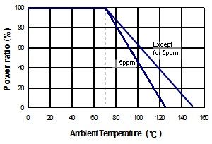
Derating Curve
Automotive grade MELF resistor with AEC-Q200 qualified to meet automotive industrial standard. Advanced level for very critical environment.
AEC-Q200 Compliance.
Thin film technology.
Excellent overall stability.
Sn termination on Ni barrier layer.
Tight tolerance down to ± 0.1%.
Extremely low TCR down to ± 10 PPM/°C.
High power rating up to 1 Watts.
SMD enabled structure.
Lead-free and RoHS compliant.
Automotive.
Industrial.
Telecommunication.
Medical Equipment.
Measurement / Testing Equipment.

| DESCRIPTION | CSRV0102 | CSRV0204 | CSRV0207 | ||||
|---|---|---|---|---|---|---|---|
| Resistance range | 8.2Ω - 1MΩ; 0Ω | 0.1Ω - 3.4MΩ; 0Ω | 0.1Ω - 3.4MΩ; 0Ω | ||||
| Resistance tolerance | ± 5%;± 1%;± 0.5%;± 0.25%;± 0.1% | ||||||
| Temperature coefficient | ± 100ppm/°C; ± 50ppm/°C; ± 25ppm/°C; ± 15ppm/°C | ± 100ppm/°C; ± 50ppm/°C; ± 25ppm/°C; ± 15ppm/°C; ± 10ppm/°C | |||||
| Operation mode | Standard | High power | Standard | High power | Standard | High power | |
| Power rating P70 | 1/8W | 1/5W | 0.3W | 1/4W | 2/5W | 1/2W | 1W |
| Operating voltage Umax. | 150V | 200V | 200V | 200V | 200V | 300V | 350V |
| Operating temperature range | -55°C ~ 155°C | ||||||
| Max. resistance change at P70 for resistance range, ΔR/R max., after 1000 h | ≦ 0.5% | ≦ 0.5% | ≦ 0.5% | ||||

|
Item Type | Power Rating at 70°C | Operating Temp. Range | Max. Operating Voltage | Max. Overload Voltage | Resistance Range | TCR (PPM/°C) | |||||||
|---|---|---|---|---|---|---|---|---|---|---|---|---|---|
| ± 0.1% | ± 0.25% | ± 0.5% | ± 1% | ± 5% | |||||||||
| 0102 | 1/8W | -55 ~ +155°C | 150V | 300V | 100Ω - 56KΩ | - | ± 15 | ||||||
| 100Ω - 82KΩ | 49.9Ω- 200KΩ | 49.9Ω - 390KΩ | - | ± 25 | |||||||||
| - | 8.2Ω - 1MΩ | ± 50 | |||||||||||
| - | 40Ω - 1MΩ | ± 100 | |||||||||||
| Jumper:2A | 0Ω (<15mΩ) | - | |||||||||||
| 0204 | 1/4W | -55 ~ +155°C | 200V | 400V | 49.9Ω - 20KΩ | ± 10 | |||||||
| 10Ω - 300KΩ | ± 15 | ||||||||||||
| 10Ω - 1MΩ | 10Ω - 3.4MΩ | 4.02Ω - 3.4MΩ | ± 25 | ||||||||||
| 10Ω - 1MΩ | 1Ω - 1MΩ | 1Ω - 3.4MΩ | 0.2Ω - 3.4MΩ | ± 50 | |||||||||
| - | 0.1Ω-1MΩ | ± 100 | |||||||||||
| Jumper:2A | 0Ω (<15mΩ) | - | |||||||||||
| 0207 | 1/2W | -55 ~ +155°C | 300V | 600V | 49.9Ω - 20KΩ | ± 10 | |||||||
| 10Ω - 300KΩ | ± 15 | ||||||||||||
| 10Ω - 1MΩ | 10Ω - 3.4MΩ | 4.02Ω - 3.4MΩ | ± 25 | ||||||||||
| 10Ω - 1MΩ | 1Ω - 1MΩ | 1Ω - 3.4MΩ | 0.2Ω - 3.4MΩ | ± 50 | |||||||||
| - | 0.1Ω - 1MΩ | ± 100 | |||||||||||
| Jumper:4A | 0Ω (<15mΩ) | - | |||||||||||
The single impulse graph is the result of 50 impulses of rectangular shape applied at one-minute intervals. The limit of acceptance was a shift in resistance of less than 1% from the initial value. The power applied was subject to the restrictions of the maximum permissible impulse voltage graph shown.
The continuous load graph was obtained by applying repetitive rectangular pulses where the pulse period was adjusted so that the average power dissipated in the resistor was equal to its rated power at 70°C. Again the limit of acceptance was a shift in resistance of less than 1% from the initial value.
Resistors are designed to function according to ohmic laws. This is basically true of resistors for frequencies up to 100kHz. At higher frequencies, there is an additional contribution to the impedance by an ideal resistor switched in series with a coil and both switched parallel to a capacitor. The values of the capacitance and inductance are mainly determined by the dimensions of the terminations and the conductive path length.
The environment surrounding components has a large influence on the behavior of the component on the printed-circuit board.
Resistors are tested in accordance with IEC 60115-1 using both 1.2/50us and 10/700us pulse shapes. The limit of acceptance is a shift in resistance of less than 0.5% from the initial value.
